- 24/7 Industrial Support Available
- +86(512)58990319
- vp@jsxtbkj.com
Industrial Rectifier Transformer (Electrochemical & Traction)
Product Overview
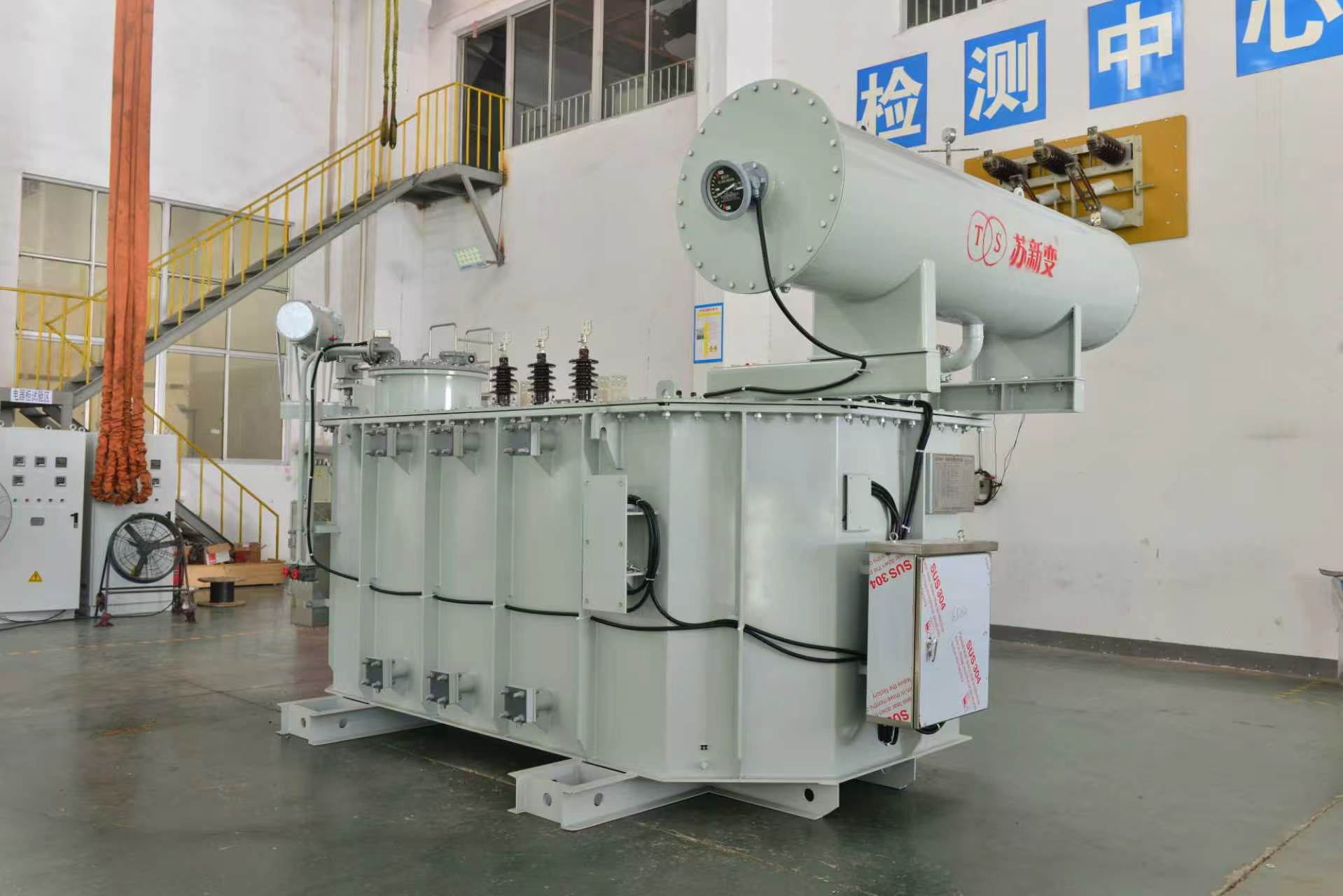
The rectifier transformer is a specialized static electrical device designed to operate in combination with diode or thyristor rectifiers to convert Alternating Current (AC) into Direct Current (DC). This transformer supplies the required isolated and regulated AC voltage to the rectifier circuit while managing the severe thermal and mechanical stresses caused by non-linear loads and heavy DC-equivalent currents. It serves as the critical power conversion interface in heavy electrochemical processes, DC traction networks, and large-scale industrial drive systems.
Key Features
1.Phase-Shifting for Harmonic Mitigation: Utilizes specialized winding configurations (such as extended delta or polygon/zigzag connections) to create precise phase angle shifts between secondary outputs. This enables the parallel operation of 12-pulse, 24-pulse, or 48-pulse rectification systems. By shifting the phase, lower-order harmonic currents are structurally canceled out on the primary AC grid according to the harmonic order equation h = np±1 (where p is the pulse number and n is an integer).
2.Thermal Design for Non-Linear Loads: The continuous operation of semiconductor valves generates high-amplitude harmonic currents, which induce severe eddy currents and localized stray heating within the transformer core and structural parts. The magnetic circuit and cooling channels are specifically sized to dissipate this excess thermal energy without exceeding specified temperature rise limits.
3.High-Current Secondary Winding Construction: To handle the massive currents required in electrolysis and smelting applications, secondary coils are wound using multiple parallel continuous transposed cables (CTC) or heavy copper busbars. This configuration minimizes 12 R copper losses and structural deformation under operational stresses.
4.Inter-Winding Electrostatic Shielding: A grounded metallic shield is installed between the primary and secondary windings. This shield minimizes capacitive coupling, preventing high-frequency switching transients generated by thyristor firing from reflecting back into the primary utility grid and protecting the primary insulation.
5.Wide-Range Voltage Regulation: Heavy-duty On-Load Tap Changers (OLTC) are integrated on the primary winding to provide fine-step voltage regulation. This allows operators to accurately control the secondary AC voltage, which directly determines the final DC output voltage required by variable-load electrochemical cells.
Technical Specifications
1.Rated Power Capacity: 1 MVA to 150 MVA (Per Unit)
2.Primary Voltage Range: 11 kV, 33 kV, 66 kV, 110 kV, 220 kV
3.Secondary Voltage Range: 100 V to 2000 V (Custom-designed to match rectifier input specifications)
4.Rectification Configurations: 6-pulse, 12-pulse, 18-pulse, 24-pulse, 36-pulse, 48-pulse
5.Cooling Method: ONAN / ONAF (Traction & Drives), OFWF / ODWF (Heavy Electrochemical)
6.Tap Changer Type: OLTC (On-Load) with up to 72 operating steps
7.Insulation Level: Class A (Mineral Oil / Silicone Fluid) or Class F/H (Cast Resin Dry-Type)
8.Phase Connection: Yd11, Dy11, Yy0, Dd0, or custom phase-shift angles (e.g., +7.5°, -7.5°)
9.Applicable Standards: IEC 61378-1, IEC 61378-2, IEEE C57.18.10
Primary Applications
1.Electrochemical Electrolysis: Powering electrolytic cells for aluminum smelting, zinc refining, copper electro-refining, and chlor-alkali (chlorine and sodium hydroxide) production.
2.DC Traction Substations: Providing rectified DC power (e.g., 750 VDC, 1500 VDC, 3000 VDC) for heavy railways, metro transit networks, and tramways.
3.Variable Frequency Drives (VFD): Serving as the input isolation transformer for large-scale industrial motor drives in mining, cement, and oil & gas operations.
4.DC Arc Furnaces: Supplying precise rectified currents for specific metallurgical melting applications requiring a DC arc.
What is the difference between a standard transformer and a rectifier transformer?
A standard transformer is designed for linear AC loads with sinusoidal currents. A rectifier transformer is specifically designed to feed a non-linear rectifier load (diodes or thyristors). It must be physically larger and thermally reinforced to handle the additional heating caused by harmonic currents, and it often includes multiple secondary windings with specific phase shifts to mitigate these harmonics.
Why are 12-pulse or 24-pulse systems used in rectifier transformers?
Standard 6-pulse rectifiers generate high levels of 5th and 7th order harmonic currents, which distort the power grid. By using a rectifier transformer with two secondary windings phase-shifted by 30° (a 12-pulse system), the 5th and 7th harmonics are mathematically canceled out. Increasing the pulse number (e.g., 24 or 48) via further phase shifting eliminates even higher-order harmonics, reducing the need for massive external harmonic filter banks.
How is the secondary AC voltage of a rectifier transformer determined?
The secondary AC voltage is dictated by the required DC output voltage of the process. For a standard three-phase full-wave diode bridge, the theoretical relationship is approximately Vdc = 1.35*Vac. Therefore, to achieve a specific DC voltage, the transformer’s secondary AC voltage is reverse-calculated, factoring in voltage drops across the diodes, commutation reactance, and internal transformer impedance.
Why is OFWF (Oil Forced Water Forced) cooling commonly used for these transformers?
In aluminum smelting and chlor-alkali applications, rectifier transformers operate continuously at maximum load, handling tens of thousands of amperes. The resulting thermal load is immense. OFWF heat exchangers pump the hot insulating oil through a water-cooled matrix, providing a significantly higher and more compact heat dissipation rate than ambient air cooling.
What causes commutation reactance in a rectifier transformer?
Commutation reactance is primarily caused by the internal leakage inductance of the transformer windings. When the current transfers (commutates) from one diode/thyristor to the next, the inductance prevents the current from changing instantaneously. This causes a brief period where two phases are short-circuited together, resulting in a slight voltage drop (notching) in the output waveform. Rectifier transformers are designed with specific impedance values to control this commutation overlap.