- 24/7 Industrial Support Available
- +86(512)58990319
- vp@jsxtbkj.com

Pad-Mounted Distribution Transformer (Single & Three-Phase)
Product Overview
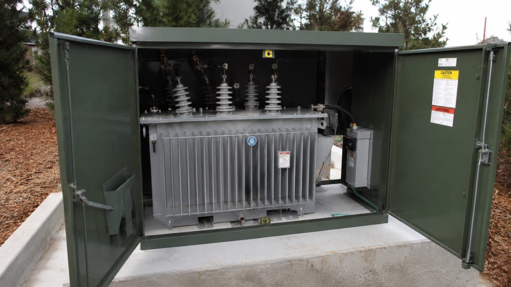
The pad-mounted transformer is a ground-level electric power distribution transformer enclosed within a locked, tamper-resistant steel cabinet and mounted on a concrete pad. Designed specifically for underground power distribution networks, this unit steps down primary utility voltage to standard utilization voltages. It integrates the core-coil assembly, high-voltage switching, and overcurrent protection devices into a single compartmentalized unit, eliminating the need for fenced-in substations and allowing for safe installation in public spaces.
Key Features
1.Tamper-Resistant Enclosure: Constructed with heavy-gauge steel, hidden hinges, and a recessed three-point latching mechanism. The enclosure complies with ANSI C57.12.28 standards for enclosure integrity, preventing unauthorized public access and ensuring safety in residential and commercial areas.
2.Compartmentalized Architecture: The cabinet is physically divided into a high-voltage (primary) compartment and a low-voltage (secondary) compartment by a grounded steel barrier. The low-voltage door must be opened first to access the internal latch for the high-voltage door.
3.Dead-Front Construction: High-voltage terminations utilize fully insulated, shielded separable connectors (loadbreak or deadbreak elbows). When the cabinet is open, there are no exposed live electrical parts on the primary side, maximizing operator safety during maintenance.
4.Integrated Overcurrent Protection: Factory-installed protective devices typically include bayonet-type expulsion fuses (for secondary faults and overload protection) placed in series with under-oil partial-range current-limiting backup fuses (for high-level primary fault isolation).
5.Loop and Radial Feed Configurations: Engineered with specific bushing layouts to accommodate either terminal (radial feed) or continuous (loop feed) underground distribution circuits. Loop feed models include internal load break switches to isolate faulted cable sections without dropping downstream loads.
Technical Specifications
1.Rated Power Capacity: 15 kVA to 167 kVA (Single-Phase) / 45 kVA to 5000 kVA (Three-Phase)
2.Primary Voltage: 2.4 kV, 4.16 kV, 12.47 kV, 13.2 kV, 24.94 kV, 34.5 kV
3.Secondary Voltage: 120/240V, 208Y/120V, 480Y/277V, 600Y/347V
4.Feed Type: Loop Feed (6 HV bushings) or Radial Feed (3 HV bushings)
5.Connection Type: Dead-Front (Standard) or Live-Front
6.Cooling Method: ONAN
7.Dielectric Fluid: Mineral Oil (Standard) or Natural Ester Fluid (High fire point, biodegradable)
8.Enclosure Material: Mild Steel, Stainless Steel 304, or Stainless Steel 316L (For severe coastal environments)
9.Applicable Standards: IEEE C57.12.34 (Three-Phase), IEEE C57.12.38 (Single-Phase), ANSI C57.12.28, DOE 2016 Efficiency / CSA C802.1
Primary Applications
1.Residential Subdivisions: Providing stepped-down power to homes via underground distribution cables where overhead lines are prohibited or aesthetically undesirable.
2.Commercial and Retail Centers: Serving shopping malls, standalone retail stores, and office parks directly from the utility grid.
3.Educational and Medical Campuses: Delivering reliable, isolated power to multiple buildings across a shared campus infrastructure.
4.Renewable Energy Generation: Functioning as step-up transformers (generator step-up, GSU) at the base of wind turbines or within utility-scale solar arrays to connect low-voltage inverters to the medium-voltage collector grid.
What is the difference between a loop feed and a radial feed pad-mounted transformer?
A radial feed transformer has one primary connection point (three high-voltage bushings) and sits at the terminal end of a distribution circuit. If the primary cable fails, the transformer loses power. A loop feed transformer has two primary connection points (six high-voltage bushings), allowing power to flow into the transformer and continue out to feed the next transformer in the chain. This provides a backup power path if one section of the cable is damaged.
What is the difference between dead-front and live-front configurations?
In a dead-front transformer, the high-voltage connections are made using insulated rubber elbows. There is no exposed conductive metal when the cabinet door is open, significantly reducing electrocution risks. In a live-front transformer, the high-voltage connections use exposed porcelain bushings and mechanical lugs, meaning live electrical components are exposed as soon as the door is opened. Dead-front is the modern standard for safety.
What are the minimum clearance requirements for installing a pad-mounted transformer?
While local utility codes vary, the industry standard requires a minimum clearance of 10 feet (3 meters) directly in front of the cabinet doors. This space is mandatory to allow line workers to use insulated fiberglass hot sticks (typically 8 feet long) to operate load break elbows and fuses safely. The sides and back generally require a minimum clearance of 3 feet (1 meter) to ensure proper airflow for cooling and to prevent fire hazards.
Why use natural ester fluid instead of standard mineral oil?
Natural ester fluid (such as FR3) is a plant-based dielectric liquid. It has a significantly higher fire point (over 300°C) compared to traditional mineral oil (around 160°C), classifying it as a less-flammable fluid. This allows the transformer to be installed closer to buildings. Additionally, ester fluid is fully biodegradable and extends the life of the cellulose paper insulation by absorbing internal moisture.
How is the transformer protected against internal faults?
Pad-mounted transformers typically use a two-fuse system. A bayonet-style expulsion fuse is accessible from the outside (using a hot stick) and melts during secondary overloads or external short circuits. For severe, high-current internal faults in the primary winding, an under-oil current-limiting fuse operates rapidly to clear the fault and limit the energy released, preventing a catastrophic tank failure.